GD&T Demystified

In the world of mechanical design, there must be consideration for the difference between dimensions given on a blueprint and the actual dimensions that result after manufacturing, since no manufacturing process is completely perfect. This variation is limited to pre-determined ranges that should be spelled out on the blueprint; these ranges are called tolerances.
For physical dimensions in mechanical design (including parts and assemblies made by processes such as machining, sheet metal stamping, and molded plastic injection molding), these tolerances have traditionally been described by a “plus” value and a “minus” value. This means that if the manufacturer cannot make the part at the exact dimension (for example, length) then the final dimension can be above or below that desired dimension by a given amount.
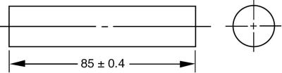
One of the most common ways to show this is by the use of the plus/minus symbol, shown as ± on a blueprint. Thus, the desired length of the part shown is 85 millimeters, but the tolerance given is ±0.4, meaning that the final length can be anywhere between 85.4 and 84.6 millimeters, including those two numbers.
While such a method is acceptable for simple dimensions such as length, width, height, and diameter, it is not always well suited when other characteristics are to be controlled, or if a part has an unusual shape where it may be difficult to describe a tolerance. Over the years, it was realized that we need more tools in our toolbox when it comes to showing tolerances on a mechanical drawing.
Thus, to better define a part, geometric dimensioning and tolerancing (GD&T) is often used as a symbolic way of showing specific tolerances on drawings. GD&T is a valuable tool that effectively communicates the design intent to manufacturing and inspection. The following drawing of a flat washer shows traditional plus/minus tolerances for the inside diameter and outside diameter (the symbol Ø means “diameter”) as well as the part’s thickness. However, each of these traditional tolerances is then supplemented by a GD&T callout; these are spelled out in the rectangular boxes, called “feature control frames.”
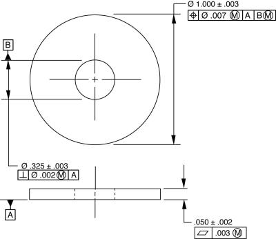
The symbol at the front of each feature control frame tells us what quality the designer wants to supplement for each of those items: the center hole has a geometric tolerance for perpendicularity, the outside diameter is being controlled for position (centering around the hole), and the GD&T symbol associated with the thickness dimension is called flatness (stating how much it can bow).
Those who do not understand GD&T sometimes ridicule it as a mysterious language that the engineer or designer uses to hold tight tolerances. But a geometric tolerance can actually give more tolerance than a conventional tolerance. Once the hurdle of learning GD&T is overcome, this mysterious language can make quality control a much more effective process, and actually saves money.
GD&T originated during the 1950s on precision military parts which needed to be produced more efficiently. The GD&T system has evolved over the last sixty years as new symbols have been added; the current standard that governs GD&T is ASME Y14.5-2009, published by the American Society of Mechanical Engineers.
The growth of GD&T was spurred by the need to overcome three disadvantages of traditional coordinate tolerancing:
- square tolerance zones
- constant tolerance values
- unclear datums
A simple example is shown below. The hole is located from the two edges using traditional plus/minus tolerancing. First, consider the shape of the imaginary tolerance zone that controls the location of the axis: it is an imaginary square of 0.5 x 0.5 mm. This means that we could manufacture a hole whose axis is at the very corner of that tolerance zone, but if we have a hole off by the same amount to the side, it would be rejected. This doesn’t make sense; if the hole at the corner was acceptable, then all holes produced at the same radius from center should function just as well.
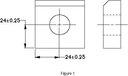
Using the GD&T symbol for position, we can translate that square tolerance to a circle of diameter 0.7 mm. By using the GD&T method to position this hole, we have increased the tolerance by 57 percent! The traditional plus/minus system doesn’t have a convenient way to describe such a circular tolerance area, but GD&T can easily do this (in the flat washer drawing shown earlier, both the hole and the outer rim are controlled with circular tolerance shapes, as shown by the symbol Ø within the feature control frames).
The second problem with the “old-fashioned” tolerancing method is that it holds the same tolerance value for each part, regardless of the actual size. In our example for the hole, let’s assume that it is simply a clearance hole that a pin will drop into. In that case, a smaller hole should be held more accurately, but a larger hole could be allowed to drift more off center, and it would still function properly. In the GD&T system, a modifier called “Maximum Material Condition” could be added to the callout to indicate that the tolerance will increase as the hole’s size increases.
The last disadvantage of this type of tolerance is the confusion about which side is to be set up on for inspection. If the part is perfectly square, it would not matter; but what if the part is made with a slight angle between the two sides? If the part is set flat against the bottom surface, then the hole should measure 24 mm from bottom, and the 24 mm from the side would have to include the gap. If we set the part flat against the side, though, we might find that the hole is only 22 mm from the side, and 26 from the bottom. Is it a good or bad part?
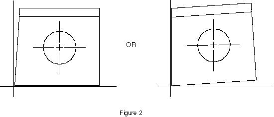
With geometric tolerancing, the designer would establish the two surfaces as “datums” and label them on the drawing with letters, such as “A” and “B,” similar to those letters shown in the flat washer example. Those datum letters would then be identified in the GD&T callout in their order of precedence. (For parts such as our example, the back face might also be identified as a datum to ensure perpendicularity.) Now every inspector would know how to set the part up without question.
It is important to note that GD&T does not necessarily replace plus/minus tolerancing; rather, it complements regular tolerances. Our preceding example could use the GD&T symbol for position to locate the hole; while other specs such as the hole size would still be shown with conventional tolerances. In all, Geometric Dimensioning and Tolerancing has fourteen symbols, each defining a different type of tolerance. While this may seem confusing at first, it allows a more precise definition of a part by giving us more tolerancing tools.
It is therefore important that everyone involved in design, manufacturing, and inspection be fluent in the GD&T language. Eogogics offers customized courses in GD&T for your group; contact us for more information or a price quote for an on-site class for your group.
Editor’s Note: John-Paul Belanger, a Principal Member of the Eogogics Engineering Faculty, is a recognized expert on GD&T. He has been teaching GD&T and related courses to engineering audiences worldwide for nearly two decades. He holds a BSE from the University of Michigan in aerospace engineering and is certified as a Senior Level GD&T Professional by the American Society of Mechanical Engineers (ASME). Eogogics tolerancing curriculum includes an intensive 2-day GD&T tutorial, a comprehensive 3-day GD&T workshop, a course on tolerance stack analysis using GD&T, and a general course on statistical tolerance analysis. Email us (info@eogogics.com) or call us (+1 703 281 3525, 1 888 364 6442) if you have any questions about our engineering curriculum.
Sorry, comments for this entry are closed at this time.